Wednesday, 14 August 2013

CONTROL PRINCIPLE - EXAMPLE 1

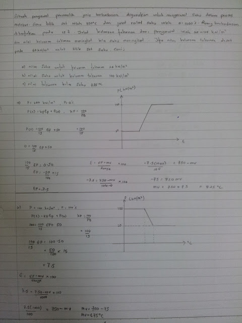
1.         A Proportional Controller is used for controlling temperature in melting process. Temperature set point is750°C and temperature measuring tool range is 0 - 1000°C .  Proportional space is set  at 15%.  Pressure output range from controller is 20 –100 kN/m2 and pressure output rises when temperature increases.  If pressure output is set at 60 kN/m2 for temperature set
            point, find
            i)          Temperature for pressure output at 20 kN/m2
            ii)         Temperature for pressure output at  100 kN/m2   

SOLUTION:
 i)          Temperature for pressure output at 20 kN/m2


ii)         Temperature for pressure output at  100 kN/m2   


2.     In a process, a Proportional Controller is used to control the liquid level in the boiler. The   
          level is set at 8 meters and the level range is 1 to 14 meters. Proportional band is at 
          20%.  The output current has a range of  5 – 20mA. Determine:-

          i.                    The output level when current is 5 mA.
         ii.                  The output current at a level of 10 meters.

SOLUTION:


3.     An air to open valve on the inflow controls level in a tank. When the process is at the set point the valve opening is 50%. An increase in outflow results in the valve  opening increasing to a new steady state value of 80%. What is the resulting offset if the controller PB is:
i)                    80%
ii)                   40%.

SOLUTION:


4.   A temperature controller has the following characteristic curve below:


      The controller has a range of 100 0C to 400 0C. The setpoint is 250 0C. Calculate:
                                                                                                                    
                                i.            The controller Proportional Band
                                                                                                                    
                               ii.            The controller Proportional Gain

SOLUTION:


Tuesday, 30 July 2013

formula for chapter 2


  • CONTROLLER OUTPUT IN PERCENT.


Controller output % =  current output -  minimum output          X 100
                                   maximum output - minimum output


  • MEASURE VALUE AS PERCENTAGE

Measure value in % =     MV - minimum MV                X 100
                                     max MV - minimum MV
  • SET POINT AS PERCENTAGE VALUE

Set point % =          SP - min value           X 100
                           max value - min value

  • ERROR AS PERCENTAGE VALUE

Error point % =            % SP X MV              X 100 
                                max value - min value

  • PROPORTIONAL BAND

Proportional band , PB =             100               
                                       proportional gain , KP

                              PB = 100
                                       KP

  • CONTROLLER OUTPUT

                              P = Kp*Ep X P(0)

  • POSITIVE ERROR BAND

Positive error band =    max permissible positive error   X100
                                             temp range

  • NEGATIVE ERROR BAND

 Negative error band = max permissible negative error   X100
                                              temp range

  • PROPORTIONAL CONTROLLER

E = SP - MV

P(i) = KP*EP + P(0)

Tuesday, 23 July 2013

CHAPTER 2

PRINCIPLES OF CONTROLLERS


2.0       EXPLANATION OF PRINCIPLES OF BASIC CONTROLLERS


The main component of controller are :

a)    Comparator mechanism
b)      Controller
c)      Feedback mechanism

Controller is a device which receives input from two points :

(i)            a value which is sent by transmitter
(ii)          a value which is set by set point

The output from the controller is send to the valve controller.
 
Figure 2.0 : Block Diagram of controller

Figure 2.0 shows the input controller is a signal which is sent by transmitter. This signal is known as a transmitter signal (MV) and set point. If the output depends on the two inputs functions well and the process is in a stable condition, then the transmitter signal is similar to the set point.  The comparator mechanism functions as comparator of both input signals. An error will exist if the input value is not the same. The detector will detect the error signal and determine if there is imbalance between error signal and feedback signals. If there is a difference, the detector will balance both of these signals. The feedback mechanism is a mechanism which balances the system. The feedback signal is always similar to the output signal.

            The main components of controller are :
(i)            Comparator mechanism. It consists of two bellows which is for transmitter signal and set point signal. Its function is to differentiate both the input signals.
(ii)          The controller consists of a flapper and nozzle. Its function is to detect the error signal from the different output and the feedback signal.
(iii)         The feedback mechanism consists of the feedback bellows. Its function is to balances and stable the system. It also has an effect towards multiple output of a controller.


2.1       EXPLANATION OF BASIC CONTROLLERS COMPONENTS

2.1.1     Bellows

 The structure of a bellow is shown in Figure 2.1. It consists of a thin metal which is formed into a wave cylinder shape. Air pressure will depress a bellow. When air pressure is increased, bellow will extend and displacement exists. This displacement is linked to the convenient‘lever’ for give the pressure increase reading. This displacement force include in mechanical force categories.


2.1.2 Flapper Nozzle
           
            Flapper nozzle is a displacement transducer which the displacement into a differential pressure parameter. Figure 2.2 shows a structure of flapper nozzle. Basically air is used as work liquid. Air will give a constant time about 0.1s. Flapper nozzle is used for measuring of displacement between load cell. This displacement is very small.

Figure 2.2 : Flapper Nozzle


2.1.3 Restrictor

                        Accuracy of an instrument is guaranteed by manufacturers only for a certain limit. Normally it is stated in the form of a full scale percent of that particular instrument. Deflection from the specification is called restrictor error.

2.2         DESIGN OF SCHEMATIC CIRCUIT FOR CONTROLLER ACTION TYPES

There are three types of controller :

a) Proportional controller
b) Integral controller

c) Derivative controller


2.2.1 Types of Controller
           
            There are a few types of controller used to control a process either in a form of Proportional output to the error, Proportional and Integral to the error or Proportional and Derivative output to the first error.
           
            Controller can be used in the form of single mode of Proportional, Integral, or Derivative, two mode of Proportional and Integral (P+I) and Proportional and Derivative (P+D), and three mode of Proportional, Integral and Derivative (P+I+D).

The figures below show the design of schematic circuit for controller action types.


(i)         Proportional Controller (P)
  

(iii)            Integral Controller 


(iv)            Derivative Controller (D)

(v)            Proportional + Integral + Derivative Controller (P+I+D)